
Introduction
As the den leader in Cub Scouts, I’ve been responsible for tracking the finishes of our yearly Pinewood Derby races. In my first year, I used my phone to record slow-motion footage and reviewed tight races to report finish results. The second year, I upgraded to a USB camera, capturing frames of the cars as they passed the finish line. I then wrote an algorithm to track the order in which the cars crossed. However, due to the limitations of the camera’s frame rate and exposure time (resulting in blurry images), the accuracy of the finishes was not as high as I had hoped. This year, I decided to improve the accuracy of the finish results while learning some new skills.
Bridging the Gap in Complex Systems
Although I’ve worked on many complex systems over the years, my focus has mostly been on software architecture, building components using APIs of existing hardware, or collaborating with a colleague on firmware development based on agreed-upon specs. This project provided an excellent platform to bridge that gap and build an embedded system from scratch.
Hardware components
Sensors
The accuracy of race times heavily depends on the sensors used to detect the finish. My previous solution relied on a camera with a 30 fps sensor, which wasn’t very sensitive and resulted in motion blur unless the cars moved at a snail’s pace or the track was brightly lit. After exploring various options, I chose the Adafruit VCNL4040 Proximity and Lux sensor. This sensor uses an Infrared LED and a photodiode to detect the amount of infrared light reflected back, determining the distance. Communication with the board is done through I2C. Its small breakout board and fast response time make it an excellent choice for tracking objects. Since my setup requires four of these I2C devices, and they all share the same address, I used an Adafruit PCA9548 8-Channel I2C Multiplexer. This solution also avoided the complications of chaining sensors in series, which would have been problematic for the physical setup.
Inputs and Display
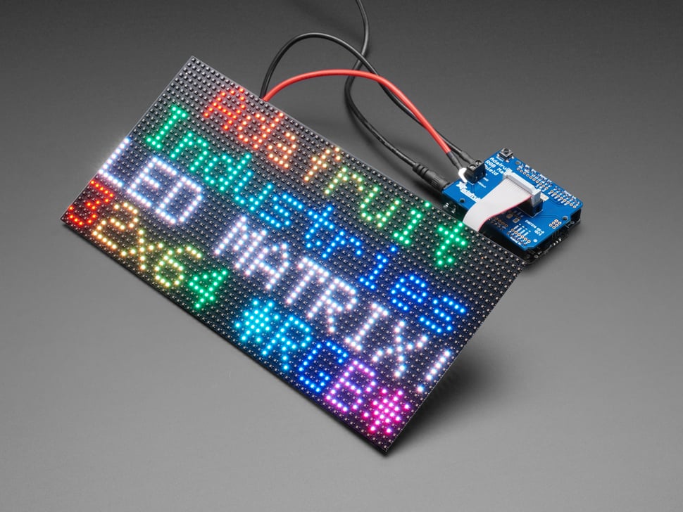
One goal is to run the system independently from a PC. I needed to define which of the four lanes would participate in the race, trigger the race start, and display the race results. To achieve this, I use toggle switches to track which lanes would participate and momentary switches to switch between various race states. The switches are connected to an Arduino Uno to read the inputs. For displaying race information, including finish results, I use a 64×32 RGB LED Matrix panel with an Adafruit RGB Matrix Shield for easy connection.
Control boards
To maximize the accuracy of the finish results, I use four Adafruit Metro Mini 328 V2 boards, each paired with one of the four VCNL4040 sensors to determine the finish time for each lane. Managing the entire system—including tracking race states, triggering race starts, displaying race results, and communicating with PCs—is done using an Adafruit Metro M4. I chose the Metro M4 over another Uno because the Uno lacks the RAM necessary to handle the 64×32 LED panel, and the M4, along with the LED panel, doesn’t have enough free inputs for the input switches.
Part summary
- Adafruit VCNL4040 Proximity and Lux sensor
- Adafruit PCA9548 8-Channel I2C Multiplexer
- Arduino Uno
- 64×32 RGB LED Matrix panel
- Adafruit RGB Matrix Shield
- Adafruit Metro Mini 328 V2
- Adafruit Metro M4
Assembly
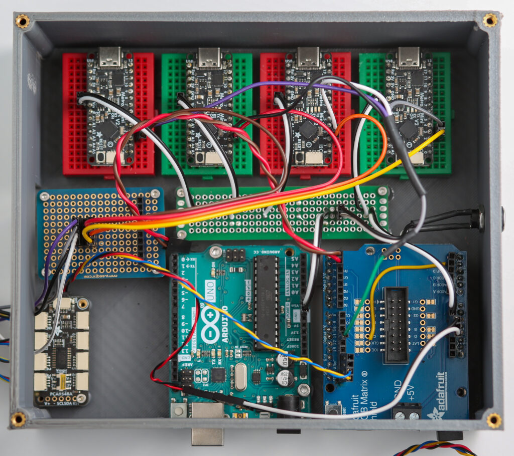
With the Metro M4 serving as the main board running the system, I connected the I2C multiplexer to the M4 via its I2C lines. On the multiplexer, the first four channels are dedicated to the VCNL4040 sensors, while the remaining four channels are connected to the Metro Mini 328 boards responsible for determining the finish time for each lane. Each lane’s interrupt pins are routed to an input pin on their respective Mini 328 boards to signal the finish. A digital output from the M4 is also routed to an interrupt pin on the Mini 328 to signal the start of the race. The Arduino Uno managed the eight switches. To read the input values, I utilize serial communication over pins 0 and 1 on both the Uno and the M4. Additionally, the RGB Matrix shield is mounted on the M4, and a 16-pin IDC connector facilitated the connection to the RGB panel.
Design considerations
The primary goal of this project is to build a system that accurately tracks race finish results, whether running independently or connected to a PC. Some design choices are made for hardware simplicity, while others are to simplify the build process. You might wonder why I use separate microcontrollers to determine the finish times for each lane instead of using the M4. This decision is due to the proximity sensors all sharing the same address, necessitating the use of a multiplexer. Switching between channels on the multiplexer takes about 10ms, so a bare-bones loop on the M4 would require 40ms to cycle through the four sensors to obtain their proximity values.
A follow-up question might be why I don’t route the interrupts from the sensors directly to the M4 instead of the Mini 328 boards. The main reason is the lack of available interrupt pins on the M4. With the RGB panel connected, the number of free pins was significantly reduced, prompting the use of an Uno for the switch inputs. Using the Mini 328 boards, each dedicated to processing start and end times via interrupts, ensured the timings are as accurate as possible.
Testing, challenges and learnings
Sensor placement
When I first received the VCNL4040 sensors, my plan was to place them above the tracks, right over the finish line, to detect noticeable changes in proximity readings as the cars crossed. Lacking access to the actual track, I had to figure out the most reliable way to detect a derby car’s crossing. I experimented with different surfaces to achieve the best change in proximity values, but I was concerned about the variability in car appearances. Whether the cars were white, black, or reflective, each would reflect IR light differently, impacting the sensor readings.
While reviewing a photo from last year’s race, I noticed there were holes in the center of each lane near the finish line. This sparked an idea: I could position the sensors below the track, allowing the cars to pass over them. This setup would cause the proximity value to change from 0 to a significantly higher number, rather than just a slight variation. This adjustment made the detection of a car crossing the finish line much more definitive.
Hardware selection musing
Building the hardware for this finish line tracker was an iterative process, assembled piece by piece. I started with an Arduino Uno and a VCNL4040 sensor, gradually upgrading components as I discovered the need for more inputs, processing power, RAM, or due to physical constraints. If I were to do it again, I would consider using the Adafruit Grand Central M4 Express. My initial hesitation was its potential incompatibility with the RGB shield for the panel. However, the Grand Central M4 offers the processing power of the M4, with ample GPIO and interrupt pins for this project. Although I’m not entirely certain that the processing loop using interrupts would be fast enough for sub-10ms detection across the four lanes (which would allow me to eliminate the four Metro Mini 328s for finish time tracking), it would at least remove the necessity for the Uno.
Conclusion
This project was a fantastic opportunity to get hands-on experience in building an embedded system from scratch. It taught me to appreciate the time and attention to detail required in such projects. Many small aspects, which I previously took for granted, can cause significant problems if not carefully managed. Stay tuned for my next post, where I’ll dive into the firmware that controls the system!
Leave a Reply